The
Tesla Coil Design, Construction and Operation Guide
by
Kevin Wilson
In conjunction with
TeslaMap - Tesla Coil Design Program
© Kevin Wilson
Table of Contents
Introduction
Design
Theory Of Operation
Power Supply
Primary Capacitance
Secondary Coil
Top Load
Primary Coil
Sample Design
Construction
Schematic
Parts
Power Supply (NST)
Primary Capacitors (MMC)
Spark Gap
Primary Coil
Secondary Coil
Top Load
PFC Capacitors
NST Protection
Line Filters
Chassis
Required Tools
Wiring
Grounding
Operation
Safety
Adjusting Gaps
Tuning
Fun
Troubleshooting
Appendix
FAQ
Helpful Links
Miscellaneous
gab
A social network that champions free speech, individual liberty and the free flow of information online. All are welcome.
Sign Up Now
Introduction
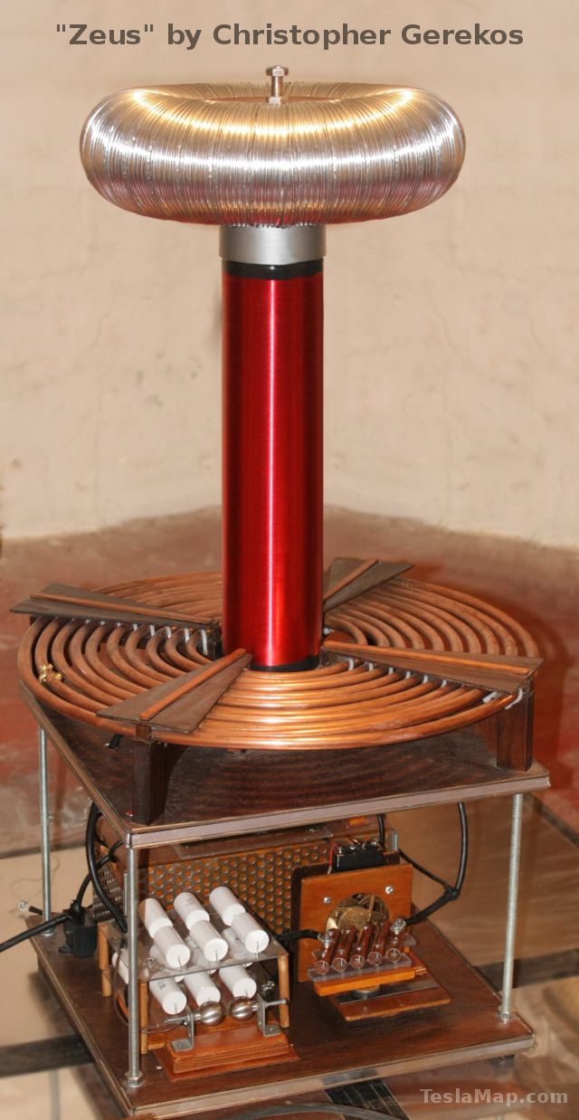 Chris Gerekos
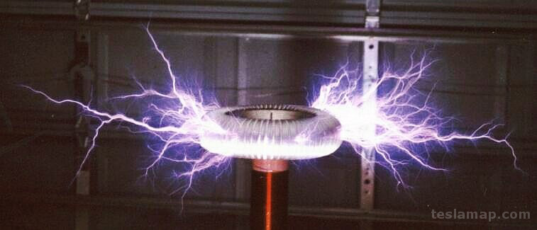
Welcome to the Tesla Coil Design, Construction and Operation Guide. I hope this guide will serve as a comprehensive step-by-step reference with easy to follow instructions. By following this guide you can build a Tesla coil capable of generating over 4' arcs of lightning.
Design
The guide will begin with a basic introduction to Tesla coils, how they operate and how to properly design one. This section mostly contains tedious equations and formulas used in the design process. Fortunately the use of software programs, like the TeslaMap Tesla coil design program can quickly and easily perform all the necessary calculations for you. If you decide to use a program, you can skip the design section and use it as a reference. This section will likely make more sense after reading the Construction section, which describes the Tesla coil parts in greater detail.
Construction
This section will guide you through the process of Tesla coil construction. I'll show you all the required parts and offer advice to help you avoid mistakes.
Operation
Finally, I'll explain how to set-up and adjust your Tesla coil for safe operation and maximum efficiency. I'll offer some troubleshooting tips to help you solve those little issues that often come up.
This guide is intended for anyone with basic to advanced experience with electronics, some free time and a desire to create their own lightning. It's helpful to have some hands-on experience with electronics, but it's not necessarily required. This guide only covers traditional Tesla coils, not solid-state Tesla coils or magnifying Tesla coils. However, all types of Tesla coils share many common parts and principles of operation so this guide may still be used as a reference for other types of Tesla coils. I try to assure that all the information in this guide is correct, but research is continually producing new techniques and old ideas are being improved or discarded. Please let me know if you have a correction or suggestion by emailing me at: contact23 at teslacoildesign.com and I'll get back to you as soon as I can.
This guide was written to be used in conjunction with the TeslaMap program. The TeslaMap program is the fastest and easiest way to design a Tesla coil. Several sample Tesla coil designs are included with the TeslaMap program. TeslaMap is ideal for quickly and easily generating a working Tesla coil design, however it is not a Tesla coil modeling program. A slightly more accurate program called JAVATC written by Bart Anderson can provide more detailed Tesla coil parameters, although it can be more difficult and time consuming to use.

Through the guide I use this type of area for information that is potentially dangerous. Please pay careful attention to this information.

Through the guide I use this type of area for information that can help you avoid common mistakes.
Please feel free to email me at: contact23 at teslacoildesign.com if you have any questions or suggestions.
Good luck building your Tesla coils!